Now it's messy, but permanent - TSB on Tire Wear, Alignment Specs
THIS BULLETIN REPLACES LA204-005, ISSUE 3.
CHANGES ARE HIGHLIGHTED WITH GREY BACKGROUND
SECTION: 204-00
Uneven Tire Wear - Repair Procedure
AFFECTED VEHICLE RANGE:
LR3 (LA) VIN: 5A000360 - 6A403382
Model Year: 2005 - 2006
CONDITION SUMMARY:
UNEVEN TIRE WEAR
Situation: A customer may report a concern of uneven tire wear. The steering alignment geometry of
certain vehicles may experience some bushing settlement during early vehicle life. Following initial
production geometry setting, this settling may alter the geometry settings outside of normal tolerance,
which may in turn increase tire wear.
Revised geometry settings introduced after 6A403382 compensate for this situation.
NOTE: This situation is not experienced on all vehicles. Toe sensitivity may be attributed to other
factors.
CAUTION: Retailers who sublet alignment to outside shops must provide the information in this
bulletin to the alignment facility to ensure proper settings when uneven tire wear symptoms are
being addressed. Additionally, all vehicles equipped with EAS sent for sublet alignment MUST
have been placed in the "tight tolerance" geometry setting mode prior to delivery using IDS. For
additional information regarding the 'tight tolerance' geometry setting mode, refer to Technical
Bulletin LA204-007.
Action: Should a customer express a specific concern of uneven tire wear, refer to the Repair Procedure
detailed in this bulletin to adjust the vehicle geometry to the "target" settings noted below.
NOTE: In other situations requiring geometry adjustment, where a specific concern of uneven
tire wear is not expressed or diagnosed, the geometry dimensions in the workshop manual should
be used. A specific set of "target" geometry data is provided in this bulletin for use in vehicles
where the geometry needs to be adjusted to correct an uneven tire wear concern.
PARTS:
No parts required
TECHNICAL BULLETIN No: LTB00116
Issue: 1
© Land Rover 2008 Page 2 of 3
WARRANTY:
NOTE: Repair procedures are under constant review, and therefore times are subject to change;
those quoted here must be taken as guidance only. Always refer to DDW to obtain the latest repair
time.
NOTE: For additional information regarding the 'tight tolerance' geometry setting mode, refer to
Technical Bulletin LA204-007.
DDW requires the use of causal part numbers.
Labor only claims must show the causal part number with a quantity of zero.
Description SRO Time
(Hours)
Condition
Code Causal Part
Place vehicle in "tight tolerance"
mode using IDS and align suspension
geometry
57.65.04 1.80 W6 ALGN4W
Normal warranty policy and procedures apply.
REPAIR PROCEDURE
ALIGN SUSPENSION GEOMETRY
1. If the vehicle has Electronic Air Suspension (EAS), refer to Technical Bulletin LA204-007, connect IDS to
the vehicle and place the Electronic Air Suspension (EAS), into "tight tolerance" geometry setting mode.
NOTE: A small number of coil sprung vehicles were imported into North America at the very start
of LR3 importation. Step 2 is included in the event that such a vehicle requires suspension
alignment.
2. If the vehicle has coil spring suspension, perform the following steps to ensure that the equivalent of a full
tank of gasoline weight is present in the vehicle when the alignment process is performed:
NOTE: LR3 fuel tank capacity is 22.7 US gallons (86.3 liters). A full LR3 fuel tank weighs
approximately 152 lbs (69 kg).
• Accurately determine the volume of fuel in the tank.
• If the tank is not full, calculate the weight of the fuel in the tank using one of the following formulas:
o Multiply the number of US gallons of fuel by 6.7 to equal total pounds of fuel.
o Multiply the number of liters of fuel by 0.8 to equal total kg of fuel.
NOTE: Any weight equivalent placed into the load space area must be evenly distributed at the
front and the right hand side of the load space.
• Calculate the weight equivalent that must be added to the load space area by subtracting the total
amount of fuel currently in the tank from the LR3 fuel tank capacity of 152 lbs. (69 kg).
NOTE: Vehicles that have any of the front or rear, upper or lower control arm bushings changed
must complete a ten mile road test before having the geometry checked and adjusted if necessary.
The road test will allow the suspension to settle.
NOTE: GTR lookup sequence is as follows:
GTR Home > NAS > Service Information/ LA – LR3 > Workshop Manuals > Bookmark
TECHNICAL BULLETIN No: LTB00116
Issue: 1
© Land Rover 2008 Page 3 of 3
"Chassis/Suspension/204-00: Suspension System – General Information" Link "Four-Wheel
Alignment (57.65.04)"
CAUTION: GTR identifies an alignment specification range.
The exact "TARGET SPECIFICATIONS" in the table below should be used on vehicles that have
experienced uneven tire wear.
When setting suspension geometry after front or rear/upper or lower control arm bushing
replacement, the rear toe should be set to the TARGET SPECIFICATION in the table.
3. Refer to GTR section 204-00 Four-Wheel Alignment operation 57.65.04 and adjust the front and rear
wheel alignment to the "TARGET" specification figures noted in the table below:
TOE ADJUSTMENT
TARGET
SPECIFICATIONS
(decimal degrees)
Front total toe + 0.14 to +0.18
Left-hand rear toe + 0.18 (Target)
Right-hand rear toe + 0.18 (Target)
Rear total toe + 0.34 to + 0.38


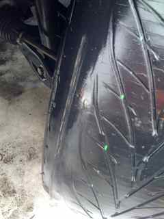
 . The entire interior of the tire was severely worn. It is in such bad condition I could see the cord! I have since thoroughly inspected the other 3 tires and notice the same interior wear but not quite as severe. Anyway... I called the dealer and they have yet to call me back on what they are going to do. Im a bit curious how a dealer ship sells a 24k vehicle with tires that are not only past the wear bar in places but showing the cords??? I am glad I caught this before the tire exploded on the highway. Any advice on how to handle this with the dealership would be appreciated.